Introduction
This article’s purpose is to explain to beginners how to do vector graphics. I’ve covered here all I needed to know to truly understand what I was doing. So, I’ll go into detail about things that are basic to some people, but that are nonetheless necessary.
If you feel like you’ve got your bases covered, you might want to check out Drawing Lines is Hard by Matt DesLauriers. It was the first article I found on the subject. It is much, much briefer. You can think of this article as what you need to understand his.
And, though this article is written around Godot, I hope it will provide a good foundation so that you can do this in whichever engine you want, and so that you can expand on it.
Why vector graphics?
I half-developed some silly games when I was a few years younger. I always got bored and eventually abandoned them. But now that I’ve started university, I’ve become friends with someone who has a lot more experience, and I’ve retroactively realized I had some Dunning-Kruger. So, I decided to work on another game.
I’d never written a game design document before; it’s one of the things my friend insisted I do that have made everything easier. For example, when writing it out I realized one of the limitations of the game was going to be my artistic ability: there’s no way I’m making 2D animations by hand that look good. But I remembered a really neat phone game called PewPew I’d played years ago, and was inspired by its neat vector graphics. So, I decided to give those a shot! How hard could it be?
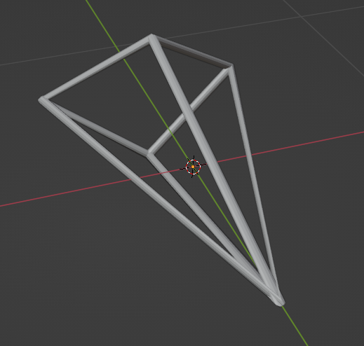
I opened Blender and made some models using only edges, and opened them up in Godot. And I saw they were being rendered as one pixel thin lines:
They weren’t very visible in big resolutions, so they wouldn’t do. Initially, I converted my model into a curve to add a bevel. That replaced every edge with a cylinder:
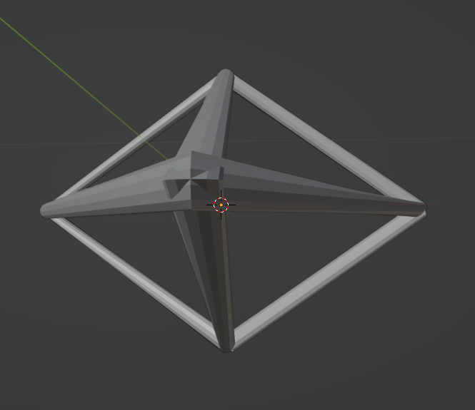
That worked alright, except where lines met:
It seemed to me like a bit of a hack, and I wanted to reach a better solution. So, I contacted the creator of PewPew, and eventually landed on their Discord server. He pointed me to Matt’s article, and I started on this journey.
Making lines have width
What is a 3D model, really? Well, it’s a bunch of arrays. The two main ones are:
- The vertex array: an indexed list of the location of every vertex, and
- The index array: the body of the model. For edge models, every pair of values corresponds to the indexes of two vertices of an edge. For face models, every triplet of values corresponds to the indexes of a triangular face.
| $$Vertex: [A, B, C]$$ $$Index: [0,1,2]$$ | 
|
When OpenGL (the API Godot uses to render) receives a model, it also receives how to interpret the index array. That’s what’s called the model’s primitive. The ship’s primitive is GL_LINES, and though OpenGL supports setting a width for the lines, Godot does not. So, as long as the model only has edges, it will be of type GL_LINES, and it will be stuck being one pixel wide.
Instead, we’ll make a new model that, for every edge the base model has, has two faces:

If you push the new vertices out perpendicularly to the old edge you get a rectangle. And that gives the line width! Except. What happens when two lines meet?

Oops… Well. How do we handle this? We take inspiration from door frames.
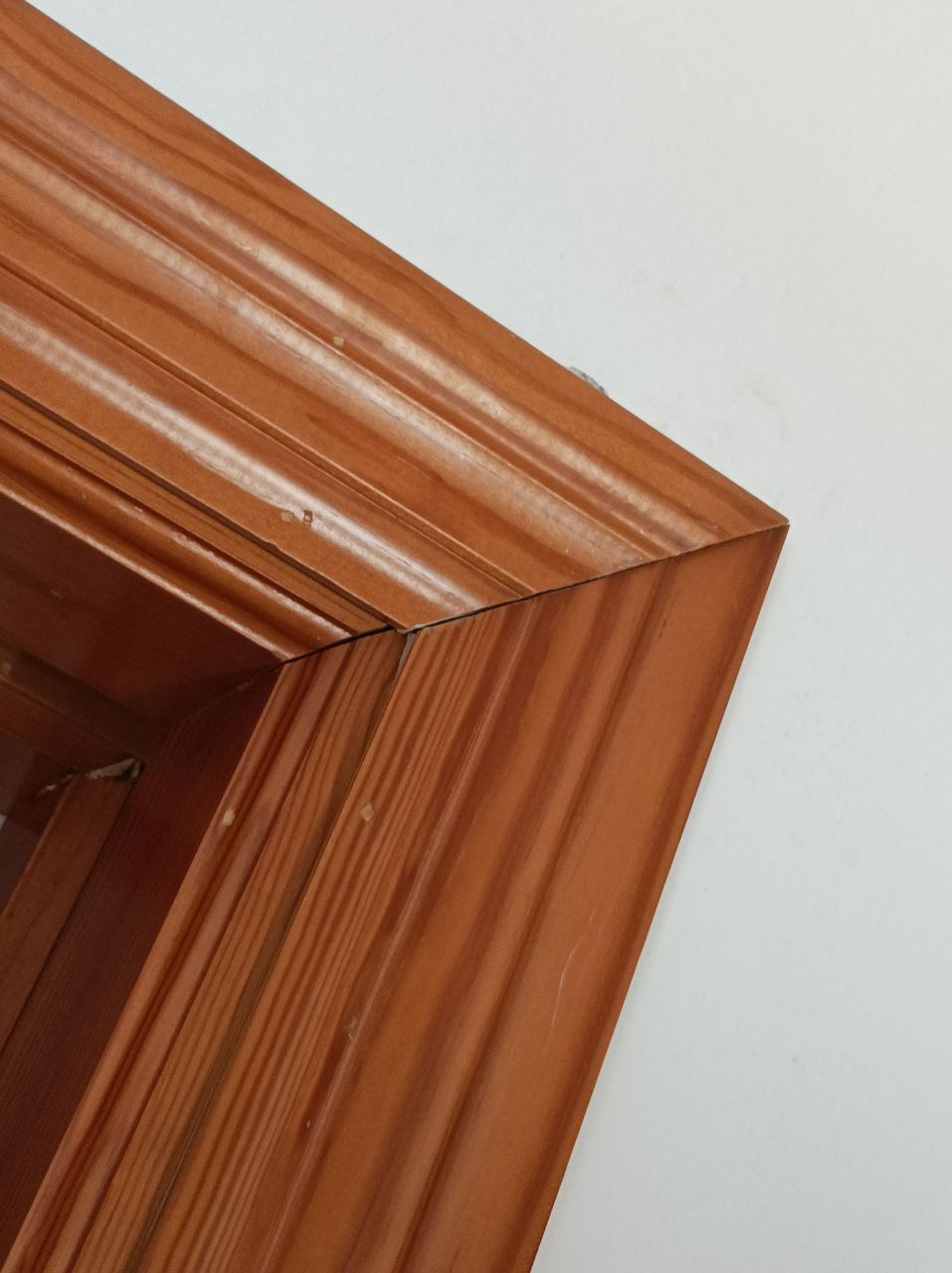
Yeah. That style of joint is called a miter joint.

Here is how you calculate $D$ and $E$:

However, there’s a problem: This really only makes sense in 2D. My game is 3D.
Shaders, screen space and rendering pipelines
So, to calculate the miter joints, we need to crunch down 3D space to a 2D plane. Specifically, we need to know where the vertices are in the screen. This is no easy task: since the camera can be constantly moving and rotating what the screen sees changes every frame. And that doesn’t take into account how the model moves around the world. Even if you’re familiar with linear algebra, this seems like a massive undertaking… Thankfully, it’s not one we have to do!
To know why, we need to get into the OpenGL rendering pipeline. After all, when the camera renders the game, it seems to project the 3D world of the game into the screen just fine. So, how does OpenGL render?
The most intuitive way to render a 3D scene would be approximating physics: casting lots of rays of light from every light source and calculating what objects they hit, how they bounce, and which hit the camera. This would be wasteful, as most rays would go flying off into the sky and would never hit the camera.
But if you simply reverse that process, casting rays from the camera and calculating what light sources they hit, you get raytracing! It’s also relatively inefficient, though: it has only recently-ish become doable in real time for consumer computers. OpenGL was made in the 90s: it has to be doing something different.
But wait, how does OpenGL project vertices?
It uses shaders! Ever heard of them? I found out about them because of Minecraft, where they seemed like magic that makes the game look cool. But what are they, really?
Well, they’re programs made to run in parallel in a graphics card. For this explanation only one type matters: the vertex shader. It runs once for every vertex in a model. By default, it projects them to the screen to calculate the vertex’s position for the raster. How does it do that? Linear algebra!
If you’re not familiar with it, I strongly recommend checking out 3Blue1Brown’s series. A vector is just a group of numbers. It can represent a position by having those numbers be its coordinates.
$$ \begin{bmatrix} x\\ y\\ z \end{bmatrix} $$
A matrix, likewise, is a grid of numbers. Multiplying a matrix by a vector can be interpreted as applying a transformation to it. For instance, this 2x2 matrix rotates a vector $\theta$ radians around the origin:
$$ \begin{bmatrix} \cos\theta & -\sin\theta \\ \sin\theta & \cos\theta \\ \end{bmatrix} \cdot \begin{bmatrix} x\\ y\\ \end{bmatrix} = \begin{bmatrix} x_\theta\\ y_\theta\\ \end{bmatrix} $$
Critically, this matrix doesn’t depend on the vector: only on the angle. That means that, given any 2D point, to rotate it around the origin you just multiply the matrix by it.
OpenGL does the same: it applies matrices to position vectors to transform them. It actually uses 4D vertices to represent 3D positions. They’re extended by adding a new value ($w$) that is always $1$. That’s because 3x3 matrices can only rotate and scale a 3D vector, but never translate. However, 4x4 matrices can translate an extended 3D vector like so: $$ \begin{bmatrix} 1 & 0 & 0 & dx\\ 0 & 1 & 0 & dy\\ 0 & 0 & 1 & dz\\ 0 & 0 & 0 & 1 \end{bmatrix} \cdot \begin{bmatrix} x\\ y\\ z\\ 1 \end{bmatrix} = \begin{bmatrix} x+dx\\y+dy\\z+dz\\1 \end{bmatrix} $$ Since these transformations keep $w$ at $1$, they can be done one after another without issue. To interpret extended vectors as a position, you simply ignore $w$.
That’s how OpenGL projects the vertices: the shader applies the appropriate matrices to each vertex’s position. All done in parallel in the graphics card. And this finally takes us to:
The rendering pipeline

Since vertices come in models, they’re given in the local space of the model. The model matrix translates, rotates and scales the model to put it in the game world (world space). This matrix changes as the model’s position updates.
The view matrix rotates the world so that the camera is at the origin facing towards $z+$. That leaves the vertices in view space, also called camera or eye space.
Finally, the projection matrix projects the vision field of the camera into a cube that goes from $[-1, -1, -1]$ to $[1, 1, 1]$. This is also where the field of view is applied, since it decides what’s actually in view of the camera. This space is called clip space because, since the cube contains everything in view, everything outside it gets clipped off.
This transformation doesn’t keep the final coordinate, $w_{clip}$, at $1$. It stores in it how far away the object was from the camera ($z_{view}$):
$$ \begin{bmatrix} …&…&…&…\\ …&…&…&…\\ …&…&…&…\\ 0 & 0 & 1 & 0 \end{bmatrix} \cdot \begin{bmatrix} x_{view}\\ y_{view}\\ z_{view}\\ 1 \end{bmatrix} = \begin{bmatrix} x_{clip}\\ y_{clip}\\ z_{clip}\\ w_{clip} = z_{view} \end{bmatrix} $$
The transformation to screen space is done by OpenGL, so it’s not controlled by the shader. To apply perspective, it divides $x_{clip}$ and $y_{clip}$ by the depth: $w_{clip}=z_{view}$. That creates a vanishing point right at the center of the screen. Then, clip space is translated so that the lower left corner of the clipping cube is at the origin. Finally, it’s scaled to the appropriate resolution. That makes the vertex’s $x$ and $y$ perfectly correspond to its corresponding pixel’s location. Finally, the triangle rasterization algorithm can take over and render the scene.
If you want to go deeper into how the matrices are actually calculated, I recommend this LearnOpenGL article.
I also recommend you take another look at the illustration and take it in. After that, we can finally take a look at what a shader does by default:
1void vertex() {
2	POSITION = PROJECTION_MATRIX * MODEL_MATRIX * VIEW_MATRIX * vec4(VERTEX, 1);
3}
Writing your own shader just means modifying what code gets you to clip space before OpenGL transforms to screen space. So, our shader will take things to screen space, calculate $\vec{u}+\vec{v}$ to reach $D$ and $E$, and then return that in clip space as the position.
 1void vertex() {
 2	vec4 vect = PROJECTION_MATRIX * MODELVIEW_MATRIX * vec4(VERTEX, 1);
 3	// Note that MODELVIEW_MATRIX is just MODEL_MATRIX * VIEW_MATRIX
 4
 5	// ... transform from clip space to screen space
 6
 7	vec4 offset = u + v;
 8
 9	// ... transform back to clip space
10
11	POSITION = offset + vect;
12}
Implementing it in Godot
The import script

If $D$ and $E$ swap places, the shape ends up looking like a B. And they do swap places when the angle crosses $180º$. So we need make more faces, turning each edge into four:

How you do that will depend a lot on the engine you’re using. In others, maybe you could do this in a Blender export script. However, you need to make sure you can pass the next and previous vertex’s positions as arguments to the shader. In Godot, the only way to pass in extra arguments is through using the custom vec4s. And I didn’t find a way to set up custom0 and custom1 from outside. So, I made an import script that modifies the mesh, populates the customs, and saves the modified mesh for later use! The structure should look something like this:
 1func process_mesh(node: MeshInstance3D):
 2  for vertex in mesh:
 3    prev = previous_vertex
 4    next = next_vertex
 5
 6    new_vertices += [vertex, vertex]
 7    new_custom0  += [(next, +1), (next, -1)]
 8    new_custom1  += [(prev, +1), (prev, -1)]
 9    # Storing the +1 and -1 here will allow us
10    # to make one u+v (D) and the other -u-v (E) in the shader
11
12  for edge in mesh:
13    new_faces += get_faces(edge)
14
15  new_mesh = generate_mesh(new_vertices, new_custom0, ...)
16
17  save(new_mesh)
There is some nuance here as this assumes that every vertex has exactly two neighbors: a previous one and a next one. This can go wrong. For example, if three edges meet in one vertex it can look very bad:

I’ve decided to handle these cases like so:
 1func process_mesh(node: MeshInstance3D):
 2  for vertex in mesh:
 3    if len(neighbors) == 1:
 4      prev = neighbors[0]
 5      next = vertex + (vertex - prev)
 6      # p -- v -- n, done to keep the end straight.
 7
 8    elif len(neighbors) == 2:
 9      prev = neighbors[0]
10      next = neighbors[1]
11
12    elif len(neighbors) == 3:
13      neighbors.sort_by_distance() # arbitrary, just looks nice in my use case.
14      next = neighbors[0]
15      prev = neighbors[1]
16      # neighbors[2] will be handled later
17
18    else:
19      continue # vertices with other ammounts of neighbors will not be processed
20
21    new_vertices += [vertex, vertex]
22    new_custom0  += [(next, +1), (next, -1)]
23    new_custom1  += [(prev, +1), (prev, -1)]
24
25    if len(neighbors) == 3:
26      extra = neighbors[2]
27      edge = get_edge(vertex, extra)
28
29      new_vertices += [vertex, vertex] # Create new vertex
30      new_custom0  += [(next, +1), (next, -1)]
31      new_custom1  += [(prev, +1), (prev, -1)]
32
33      edge = (new_vertex, edge[1])
34      # change the edge to go to the new vertex instead
35
36  for edge in mesh:
37    new_faces += get_faces(edge)
38
39  new_mesh = generate_mesh(new_vertices, new_custom0, ..)
40
41  save(new_mesh)
You can see the actual source code here.
The shader
As said, the miter joints need to be done in screen space. So, the shader applies perspective and scales with the resolution before calculating the offset for $D$ and $E$, then undoes it after.
 1shader_type spatial;
 2render_mode cull_disabled;
 3
 4uniform float thickness;
 5
 6void vertex() {
 7	vec4 vect = PROJECTION_MATRIX * (MODELVIEW_MATRIX * vec4(VERTEX, 1));
 8
 9	if (CUSTOM0.w * CUSTOM0.w < 0.1) {
10		/* This runs if CUSTOM0 is not set.
11		It's done so you can see what the model looks like in the editor if it's not been processed */
12
13		POSITION = vect;
14
15	}
16
17	vec4 next = PROJECTION_MATRIX * (MODELVIEW_MATRIX * vec4(CUSTOM0.xyz, 1));
18	vec4 prev = PROJECTION_MATRIX * (MODELVIEW_MATRIX * vec4(CUSTOM1.xyz, 1));
19
20	vec2 scaling = vec2(VIEWPORT_SIZE.x/VIEWPORT_SIZE.y, 1.);
21	vec2 inv_scaling = vec2(VIEWPORT_SIZE.y/VIEWPORT_SIZE.x, 1.);
22
23	vec2 A = prev.xy * scaling / prev.w;
24	vec2 B = vect.xy * scaling / vect.w;
25	vec2 C = next.xy * scaling / next.w;
26
27	vec2 AB = normalize(A-B);
28	vec2 CB = normalize(C-B);
29	float cosb = dot(AB, CB);
30	vec2 offset;
31
32	if (cosb * cosb > 0.99) { // If AB and CB are parallel
33		// Done so you don't take the inverse square root of 0.
34		offset = vec2(-AB.y, AB.x) * CUSTOM0.w;
35	}
36	else {
37
38		float isinb = inversesqrt(1. - cosb * cosb);
39
40		// CUSTOM0.w is +1 or -1 to reach either D or E
41		vec2 u = AB * CUSTOM0.w * isinb;
42		vec2 v = CB * CUSTOM0.w * isinb;
43
44		offset = u + v; // Offset to reach D and E
45
46	}
47
48	POSITION = vect + vec4(offset * inv_scaling * thickness,0,0);
49
50}And now, with the miter joint, things should just look amazing!
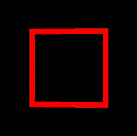
Woah! That… What? Why does it do that?
… Well. You can see if you play around in GeoGebra that when the angle gets sharp the joint gets really long… In fact, as the angle becomes 0º the length goes up to infinity. So, an easy solution might be to add a limit to the distance the joint can have from its original point.
45float excess = length(offset) - limit;
46
47if (excess > 0.) {
48	offset = normalize(offset) * limit;
49}
…Huh. Ok, now it doesn’t go to infinity anymore. But now the lines get thinner…

Of course, that makes sense. The length of the joint needed to go up to infinity to preserve the width. So, if we cap it, it loses width…
Except. I have an idea! There are actually two other points where the lines cross when making miter joints! As $D$ and $E$ stretch towards infinity, these other points come closer:

So what if we just, after a certain threshold, just stop using $D$ and $E$ and start using $F$ and $G$? Let’s call that a switcheroo limit:
45float excess = length(offset) - limit;
46
47if (excess > 0.) {
48	offset = u - v; // Switch to F and G
49}
Well, it works. It remains just as wide, but now the edge is gone… Which makes sense, of course. But it looks weird when the edge suddenly disappears. And I can’t think of a way to transition smoothly using only those two vertices. Is there a way we can preserve both the sharp pointy edge and the width?
Luz joints!
Yes! Since we want the thickness to be preserved, we can do a switcheroo. But we also want the pointiness not to grow to infinity. So, we add another vertex and another face!

$L$ normally stays still. But when the length starts growing up to infinity, we first do a switcheroo to $F$ and $G$, and then put $L$ where the tip would be, limiting its distance. Here are the import script and shader for this:
 1func process_mesh(node: MeshInstance3D):
 2  for vertex in mesh:
 3    # ... neighbor logic
 4
 5    prev = previous_vertex
 6    next = next_vertex
 7
 8    new_vertices += [vertex, vertex]
 9    new_custom0  += [(next, +1), (next, -1)]
10    new_custom1  += [(prev, +1), (prev, -1)]
11
12    # Luz joint! (L vertex)
13    new_vertices += [vertex, vertex]
14    new_custom0  += [(next, +1), (next, -1)]
15    new_custom1  += [(prev, -1), (prev, +1)]
16    # Having different sign accross the customs will allow us to detect them in the shader
17
18    # ... 3 neighbor logic
19
20  for edge in mesh:
21    new_faces += get_faces(edge)
22
23  new_mesh = generate_mesh(new_vertices, new_custom0, ...)
24
25 save(new_mesh) 1shader_type spatial;
2render_mode cull_disabled;
3
4uniform float thickness;
5uniform float limit;
6
7
8void vertex() {
9 vec4 vect = PROJECTION_MATRIX * (MODELVIEW_MATRIX * vec4(VERTEX, 1));
10
11 vec4 next = PROJECTION_MATRIX * (MODELVIEW_MATRIX * vec4(CUSTOM0.xyz, 1));
12 vec4 prev = PROJECTION_MATRIX * (MODELVIEW_MATRIX * vec4(CUSTOM1.xyz, 1));
13
14 vec2 scaling = vec2(VIEWPORT_SIZE.x/VIEWPORT_SIZE.y, 1.);
15 vec2 inv_scaling = vec2(VIEWPORT_SIZE.y/VIEWPORT_SIZE.x, 1.);
16
17 vec2 A = prev.xy * scaling / prev.w;
18 vec2 B = vect.xy * scaling / vect.w;
19 vec2 C = next.xy * scaling / next.w;
20
21 vec2 AB = normalize(A-B);
22 vec2 CB = normalize(C-B);
23 float cosb = dot(AB, CB);
24 vec2 offset;
25
26 if (cosb * cosb > 0.999999) { // If AB and CB are parallel
27 if (CUSTOM0.w == CUSTOM1.w) { // Normal vertex
28 offset = vec2(-AB.y, AB.x) * CUSTOM0.w;
29 }
30 else { // L vertex
31 offset = AB * CUSTOM0.w * limit; // Push it out by max length
32 }
33 }
34 else {
35
36 float isinb = inversesqrt(1. - cosb * cosb);
37
38 vec2 u = AB * CUSTOM0.w * isinb;
39 vec2 v = CB * CUSTOM1.w * isinb;
40
41 if (CUSTOM0.w == CUSTOM1.w) { // Normal vertex
42 if (cosb > 0.) {
43 offset = u - v; // Use F and G
44 } else {
45 offset = u + v; // Use D and E
46 }
47 } else { // L vertex
48 if (cosb > 0.) {
49 offset = u - v; // Use L
50 } else {
51 offset = vec2(0., 0.); // Don't use L
52 }
53
54 float excess = length(offset) - limit;
55
56 if (excess > 0.) {
57 offset = normalize(offset) * limit;
58 }
59
60 }
61
62 }
63
64 POSITION = vect + vec4(offset * inv_scaling * thickness,0,0);
65
66 if (CUSTOM0.w * CUSTOM0.w < 0.1) {
67
68 POSITION = vect;
69
70 }
71}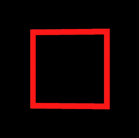
There we go! The width and edge are both preserved!
And now, for the grand finale, let’s see what it looks like on the ship I’ve made!

Endnote
…so. bit of a journey, ey?
When I started making this, I didn’t know anything about OpenGL, shaders, Blender or Godot. I expected this to be an easy, short project. But, as you’ve seen, it was nothing but.
As I learned more, I was worried making it work might be way beyond my skill and knowledge. But by breaking down the problem, learning about the basics, and finding more knowledgeable people, I ended up getting it done!
It was hard, but that’s why I get to write an article about it.